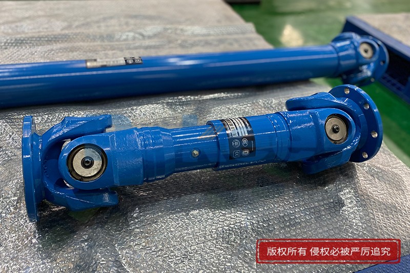
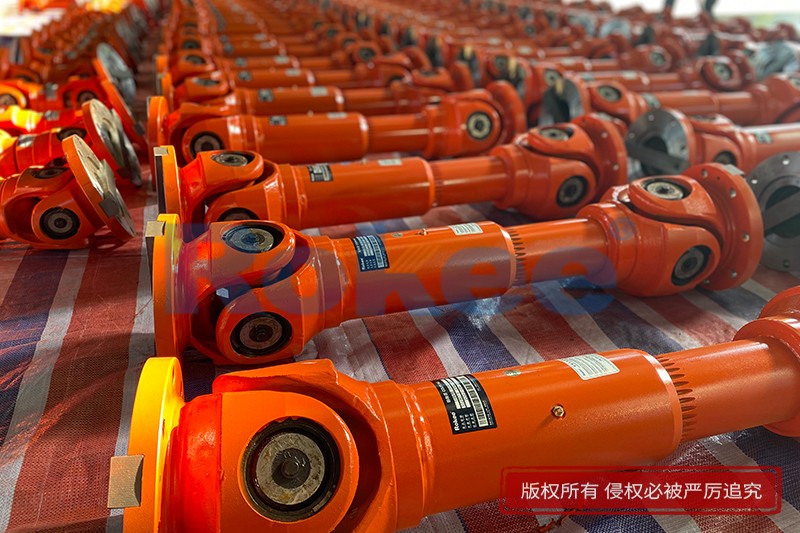
Industrial Cardan Shafts Schematic Diagram
Rokee® is a well-known high-quality industrial cardan shaft supplier from china, learn more about industrial cardan shafts schematic diagram, pls contact Rokee technology. Rokee has been established in China since 1999, over the years, with excellent quality, we have been continuously providing many industrial cardan shaft products of various categories and uses complying with multiple standards and a full range of services, from the industrial cardan shaft selection to final installation and operation, for the industry fields of ferrous metallurgy, nuclear power, gas turbine, wind power, ropeway construction, lifting transportation, general equipment, etc.
The industrial cardan shaft uses cross bearings to connect the flanges at both ends, which can transmit torque that is not on the same axis. The diagonal compensation can reach more than 25°, and the spline connection can compensate for the axial displacement in a large distance. With high carrying capacity and excellent transmission efficiency, industrial cardan shaft is widely used in modern industrial fields.
Industrial Cardan Shaft Products
-
ROWS-BH Cardan Shaft
View More -
ROWL-BH Cardan Shaft
View More -
ROWM-BH Cardan Shaft
View More -
ROWH-BH Cardan Shaft
View More -
ROWS-WD Cardan Shaft
View More -
ROWM-WD Cardan Shaft
View More -
ROWH-WD Cardan Shaft
View More -
ROWL-WD Cardan Shaft
View More -
ROWM-WH Cardan Shaft
View More -
ROWH-WH Cardan Shaft
View More -
ROWL-WH Cardan Shaft
View More -
ROWS-WH Cardan Shaft
View More -
SWC-BH Universal Coupling
standard telescopic welded
View More -
SWC-CH Uuniversal Coupling
Long Telescopic Welded
View More -
SWC-DH Universal Coupling
Short Telescopic Welded
View More -
SWC-WD Universal Coupling
Non-telescopic Short
View More -
SWC-WH Universal Coupling
Non-telescopic Welded
View More -
SWP-A Universal Coupling
Long Type, Telescopic
View More -
SWP-B Universal Coupling
Short Type, Telescopic
View More -
SWP-C Universal Coupling
Short Type, Non-telescopic
View More -
SWP-D Universal Coupling
Long Type, Non-elescopic
View More
« Industrial Cardan Shafts Schematic Diagram » Post Date: 2024/4/7
URL: http://www.rokee.com/en/blog/industrial-cardan-shafts-schematic-diagram.html
Tags: Industrial Cardan Shafts ,


